Home
/
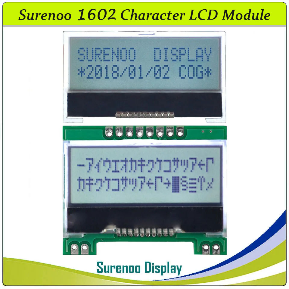
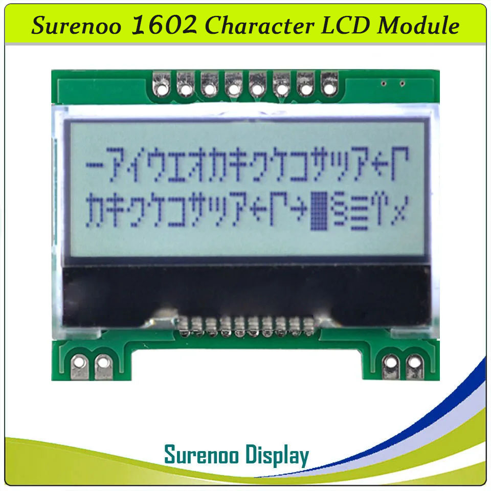
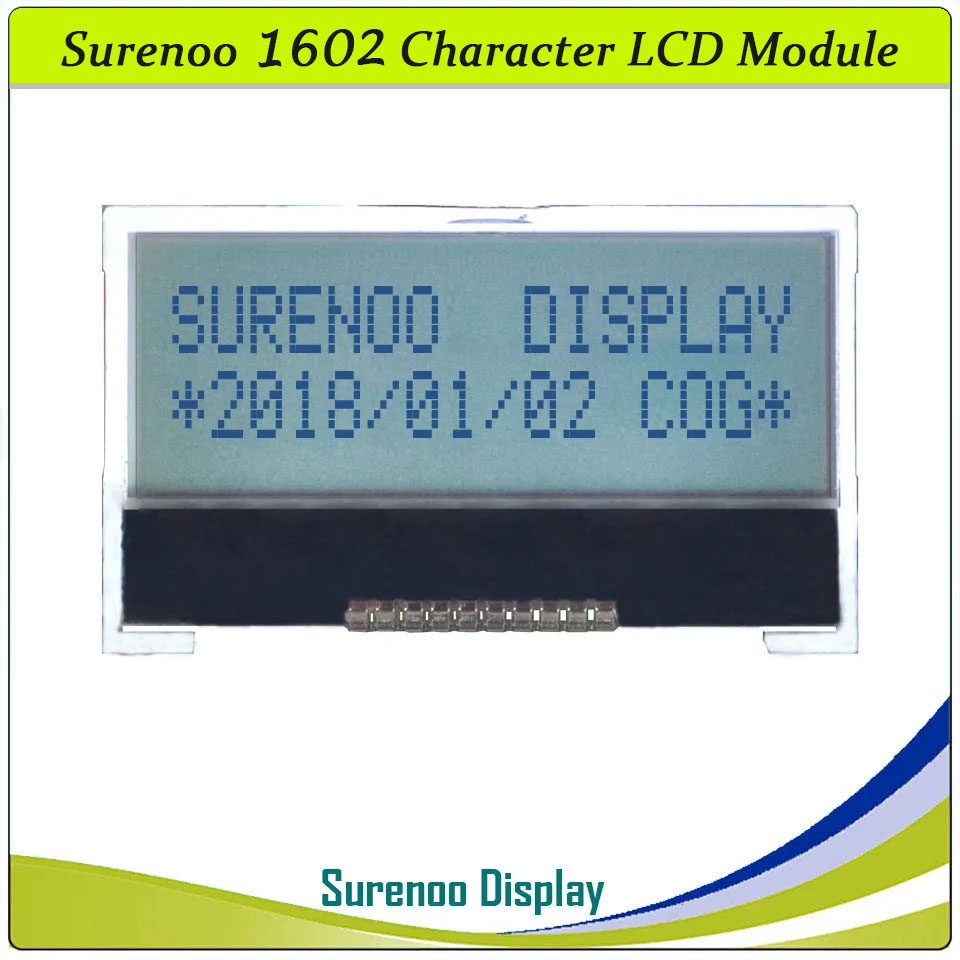
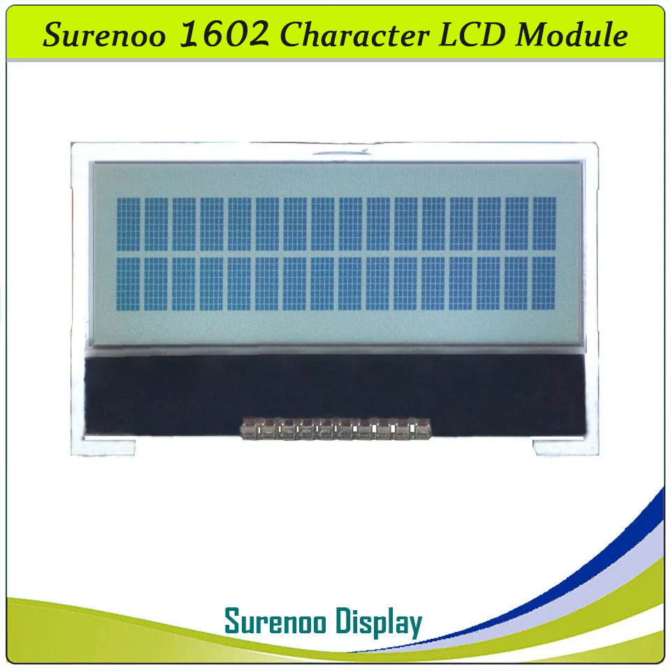
SLC1602I PCB=41.50X33.30MM 1602 16*2 COG Surenoo Character LCD Module Display Screen Panel Integrated Serial SPI ST7032 Controller FSTN Positive LCD with White LED Backlight for Arduino UNO Nano Mega2560
SLC1602I PCB=41.50X33.30MM 1602 16*2 COG Surenoo Character LCD Module Display Screen Panel Integrated Serial SPI ST7032 Controller FSTN Positive LCD with White LED Backlight for Arduino UNO Nano Mega2560
WISHLIST
Model No.: SLC1602I
Display Format: 16X02 Characters
PCB Size: 66.70*37.46MM
Controller: ST7032s or Equal
Display Format: 16X02 Characters
PCB Size: 66.70*37.46MM
Controller: ST7032s or Equal
11 sold
Quantity
-
Detail
- Overview
It's easily controlled by ARDUINO and Raspberry Pi. It can be used in any embedded systems, industrial device, security, medical and hand-held equipment.
- Specification
Gross Weight 0.020Kg Manufacturer Surenoo Display Type Character LCD Module Continuity Supply More than 10 years Part No. SLC1602I Display Format 16x2 Character Interface Integrated Serial SPI IC or Equivalent ST7032 or Equal Fonts English-Japanese Voltage(Type) 3.3V in default Connection IP: 1X10P/1.5 Iron Pin
IM: 1X8P/2.54 Pin HeaderOutline Dimension IP: 41.50(W)x24.30(H)x3.90(T)mm IM: 41.50(W)x33.30(H)x4.90(T)mm Visual Area 37.60x13.80mm Active Area 34.21x8.76mm Display Type FSTN Positive Backlight Type (LED) White LED IC Package COG Viewing Direction 6:00 O'Clock Operating Temperature-20℃~70℃Storage Temperature-30℃~80℃- Outline Drawing
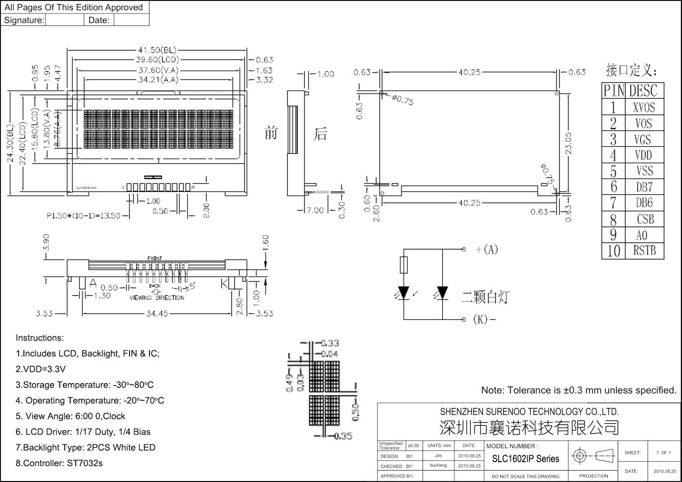
2. SLC1602IM Series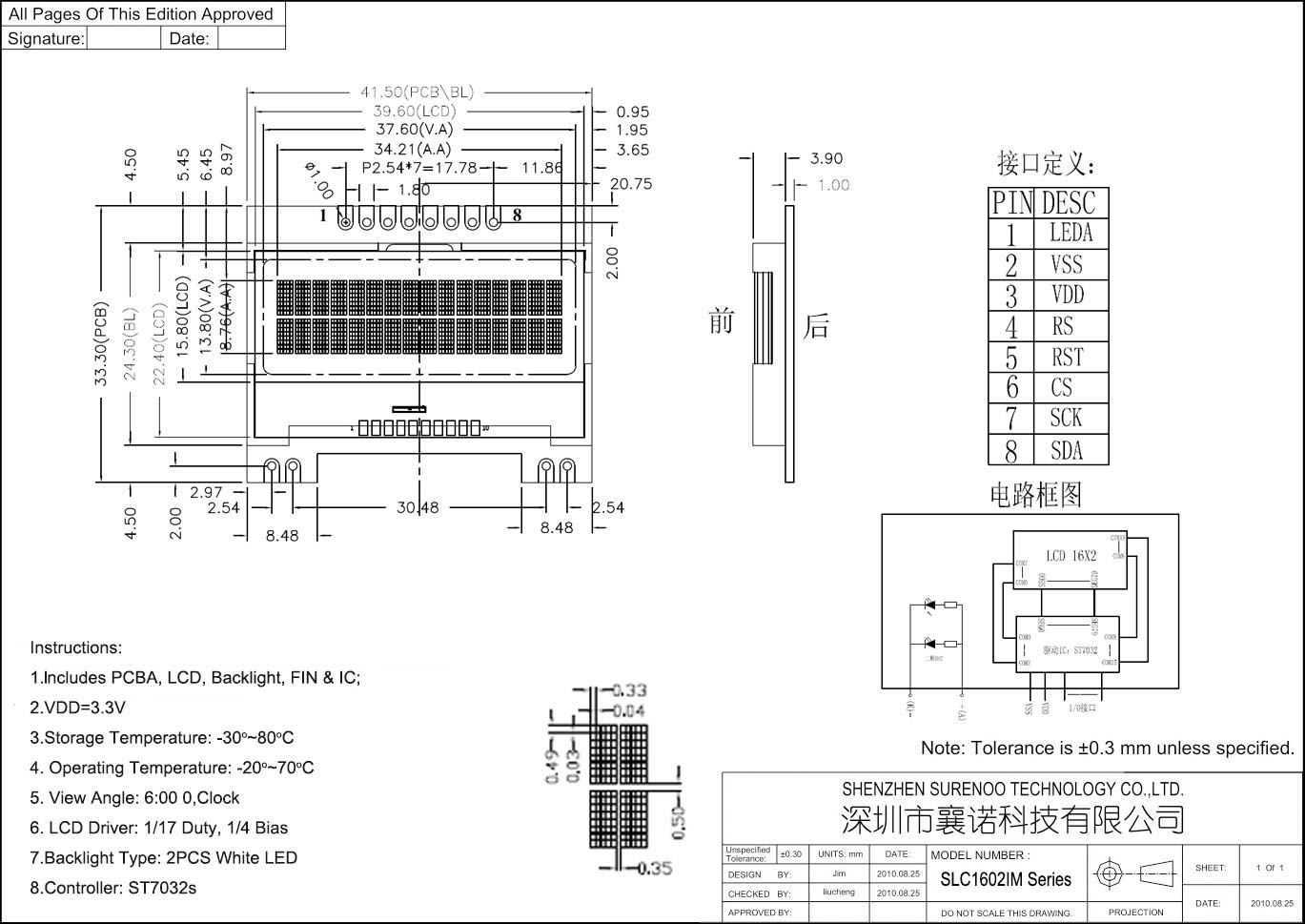
- Interface
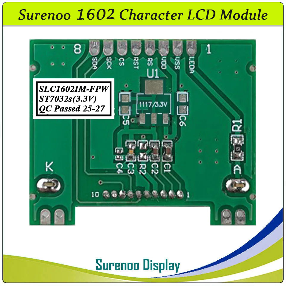
Pin No. Symbol Description Pin No. Symbol Description SLC1602IP (Without PCB Adapter) SLC1602IM (With PCB Adapter) 1 XV0S Bias Voltage (Insert 1uF Capacitor between them) 1 LEDA Power Suppy for Backlight (3.3V) 2 V0S 2 VSS Ground 0V 3 VGS Bias Voltage (Insert 1uF Capacitor between VGS and VDD) 3 VDD Logic Power Supply (3.3V) 4 VDD Logic Power Supply (3.3V) 4 A0(RS) Register Selection Singal (H: Data Register; O: Command Register) 5 VSS Ground 0V 5 RST Reset Pin 6 D7(SDA) Serial Data Signal 6 CSB Chip Selelction 7 D6(SCL) Serial Clcok Signal 7 SCK Serial Clock Signal 8 CSB Chip Selection 8 SDA Serial Data Signal 9 A0(RS) Register Selection Singal (H: Data Register; O: Command Register) 10 RST Reset Pin BLA & BLK: 3.3V
-
Customer ReviewsNo comments

