
Home
/
SLC2402A PCB=118.00X36.00MM 2402 24*2 Surenoo Character LCD Module Display Screen Panel 6800 4-/8- Bbit Parallel Serial IIC I2C RS232 UART TTL AIP31066 SPLC780D ST7066 PCF8574T Controller USB2LCD LCD2USB LCD Smartie AIDA64
SLC2402A PCB=118.00X36.00MM 2402 24*2 Surenoo Character LCD Module Display Screen Panel 6800 4-/8- Bbit Parallel Serial IIC I2C RS232 UART TTL AIP31066 SPLC780D ST7066 PCF8574T Controller USB2LCD LCD2USB LCD Smartie AIDA64
WISHLIST
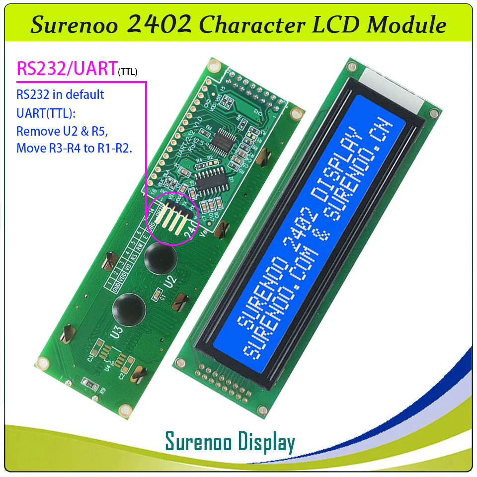
Model No.: SLC2402A
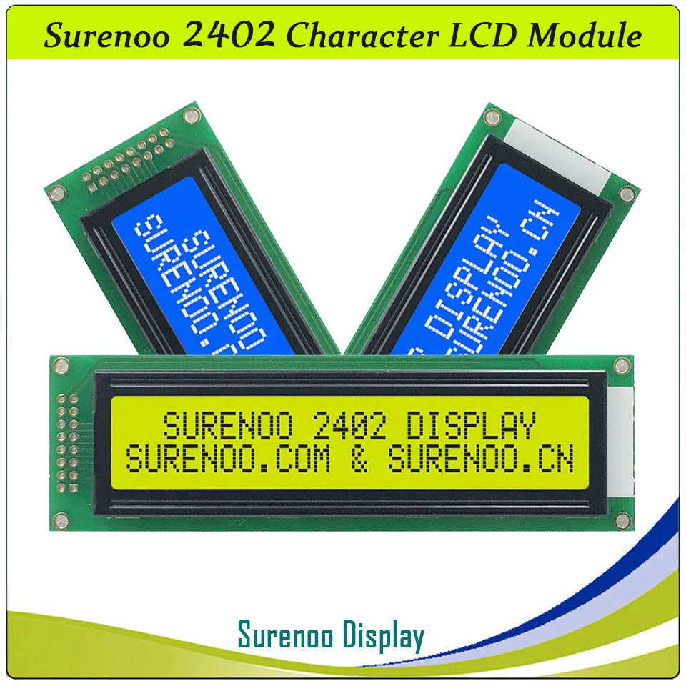
Display Format: 24X02 Characters
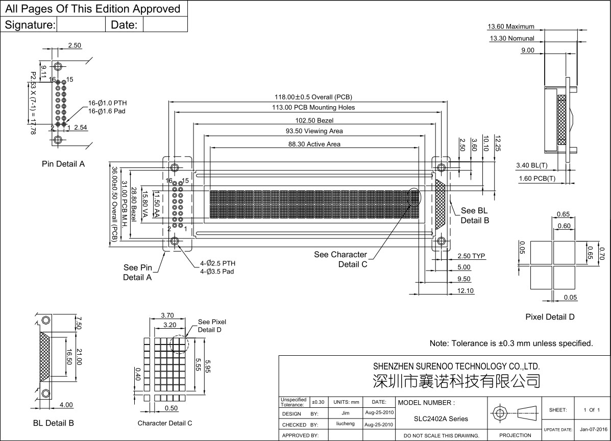
PCB Size: 118.00X36.00MM
Controller: AIP31066, ST7066 or Equal
Display Format: 24X02 Characters
PCB Size: 118.00X36.00MM
Controller: AIP31066, ST7066 or Equal
210 sold
Quantity
-
Detail
- Overview
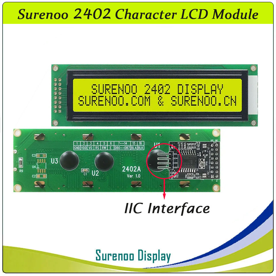
SLC2402A is 24 characters wide, 2 rows character lcd module, AIP31066 controller (Industry-standard HD44780 compatible controller), 6800 4/8-bit parallel interface, wide operating temperature range, RoHS Compliant, built in character set supports English-Japanese, see the AIP31066 datasheet for the full character set. It's 5V or 3.3V power supply, and I2C adapter board is optional for Arduino.
It's easily controlled by MCU such as 8051, PIC, AVR, ARDUINO, ARM and Raspberry Pi. It can be used in any embedded systems, industrial device, security, medical and hand-held equipment.- Specification
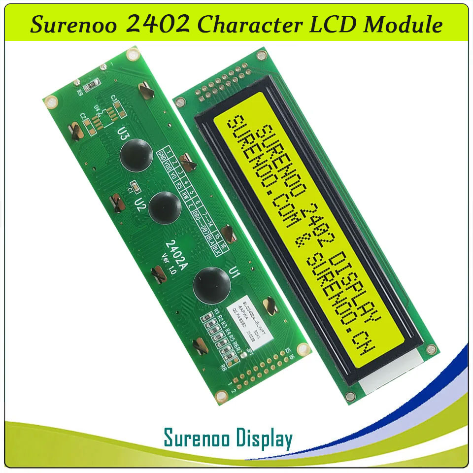
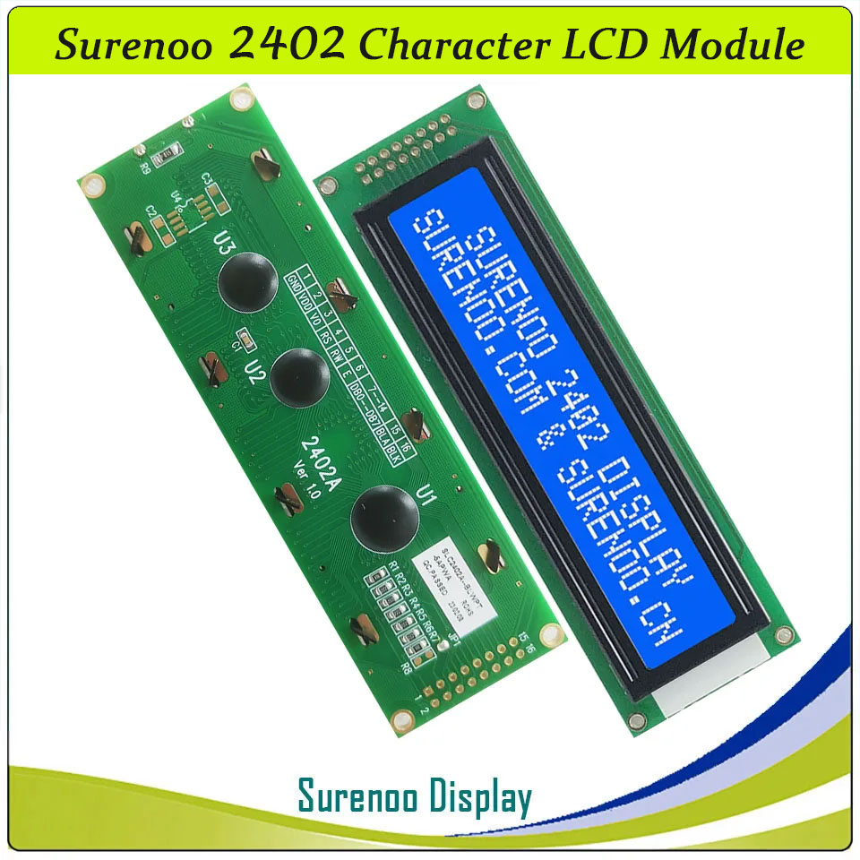
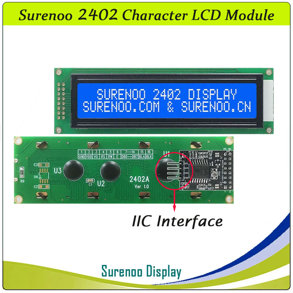
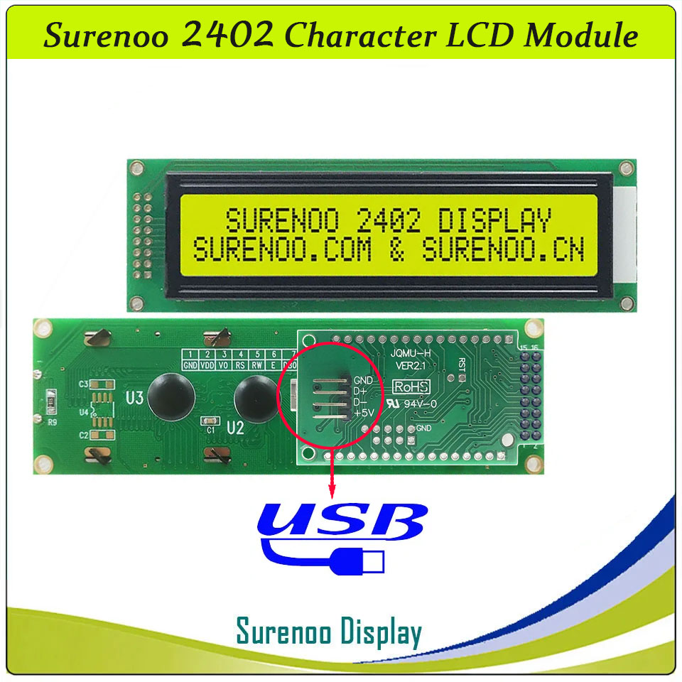
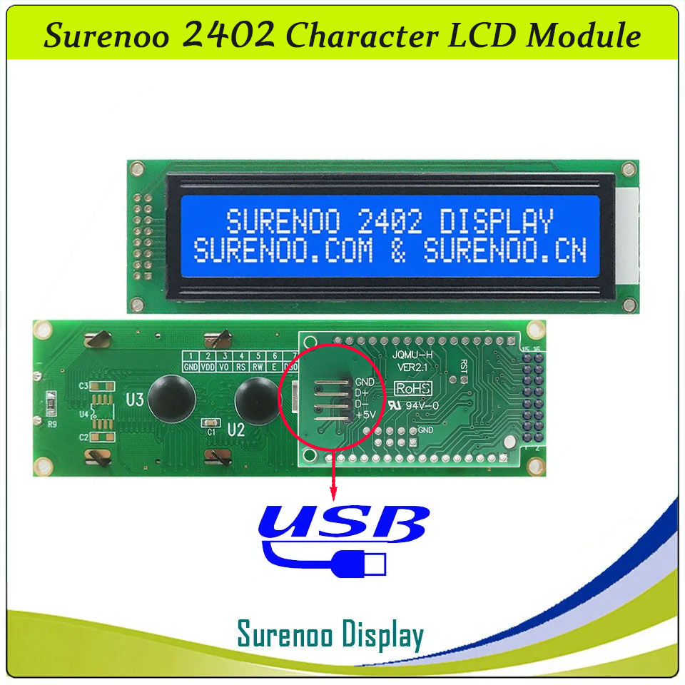
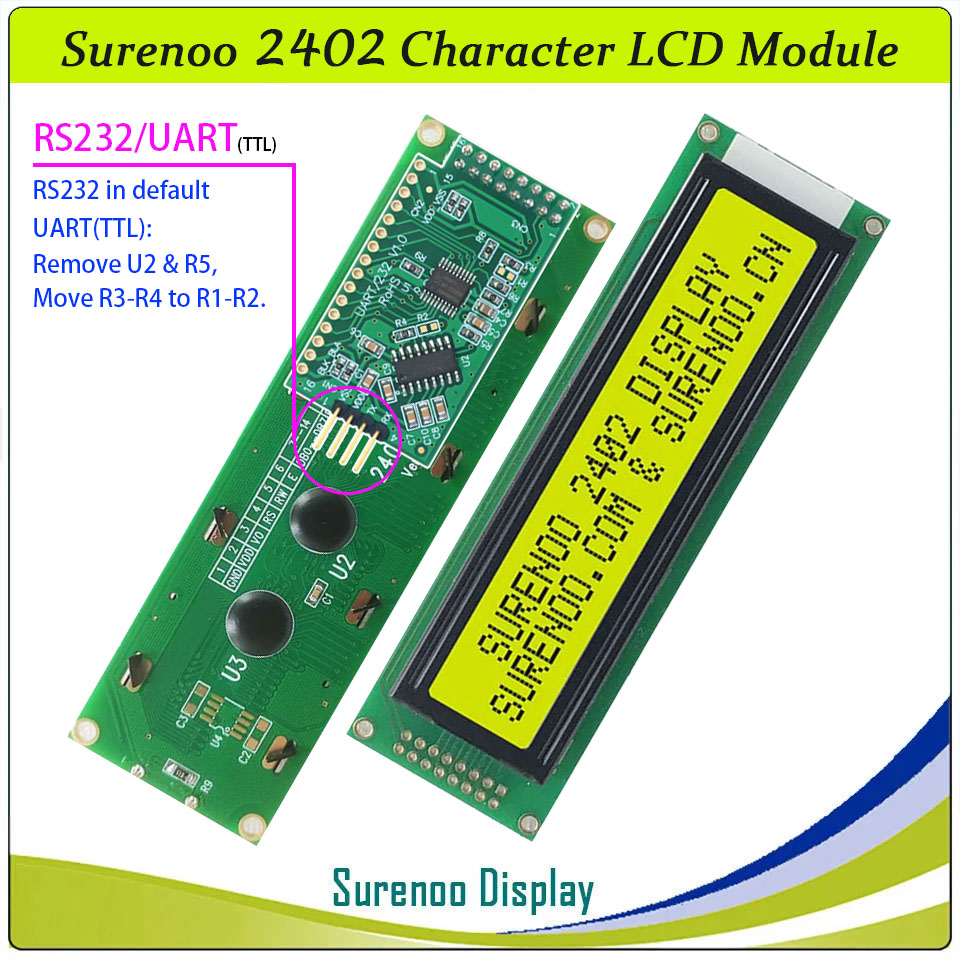
Gross Weight 0.060Kg Manufacturer Surenoo Display Type Character LCD Module / IIC Display / USB Display Continuity Supply More than 10 years Part No. SLC2402A Display Format 24x2 Character Interface 6800 4-bit Parallel, 6800 8-bit Parallel, Serial IIC, Serial LCD2USB, RS232/UART(TTL) IC or Equivalent AIP31066, ST7066 or Equal Fonts English-Japanese Voltage(Type) 5.0V in default, 3.3V is Optional Connection 2X8P/2.54 Pin Header Outline Dimension 116.00(W)x36.00(H)x13.60(T)mm Visual Area 93.50x15.80mm Active Area 88.30x11.50mm Display Type STN LCD-Yellow Green, STN Blue Negative Backlight Type (LED) Yellow Green, White IC Package COB Viewing Direction 6:00 O'Clock Operating Temperature-20℃~70℃Storage Temperature-30℃~80℃- Outline Drawing
- Interface
Pin No. Pin Symbol Description 1 VSS Ground 0V 2 VDD Logic Power Supply 3 V0 Operating voltage for LCD 4 RS Data / Instruction Register Select (H: Data Signal, L: Instruction Signal) 5 R/W Read / Write (H: Read Mode, L: Write Mode) 6 E Enable Signal 7-14 DB0-DB7 Data Bus 15 LED_A Backlight Anode 16 LED_K Backlight Cathode -
Customer ReviewsNo comments