
Home
/
Surenoo Graphic OLED Module 75.00MMX52.70MM 2.42" 12864 128*64 128X64 Graphic LCD Module Display Screen Panel PM-OLED 6800/8080 8-Bit Parallel 4-Wire Serial SPI IIC I2C SSD1309 Controller SOG12864B2_M242
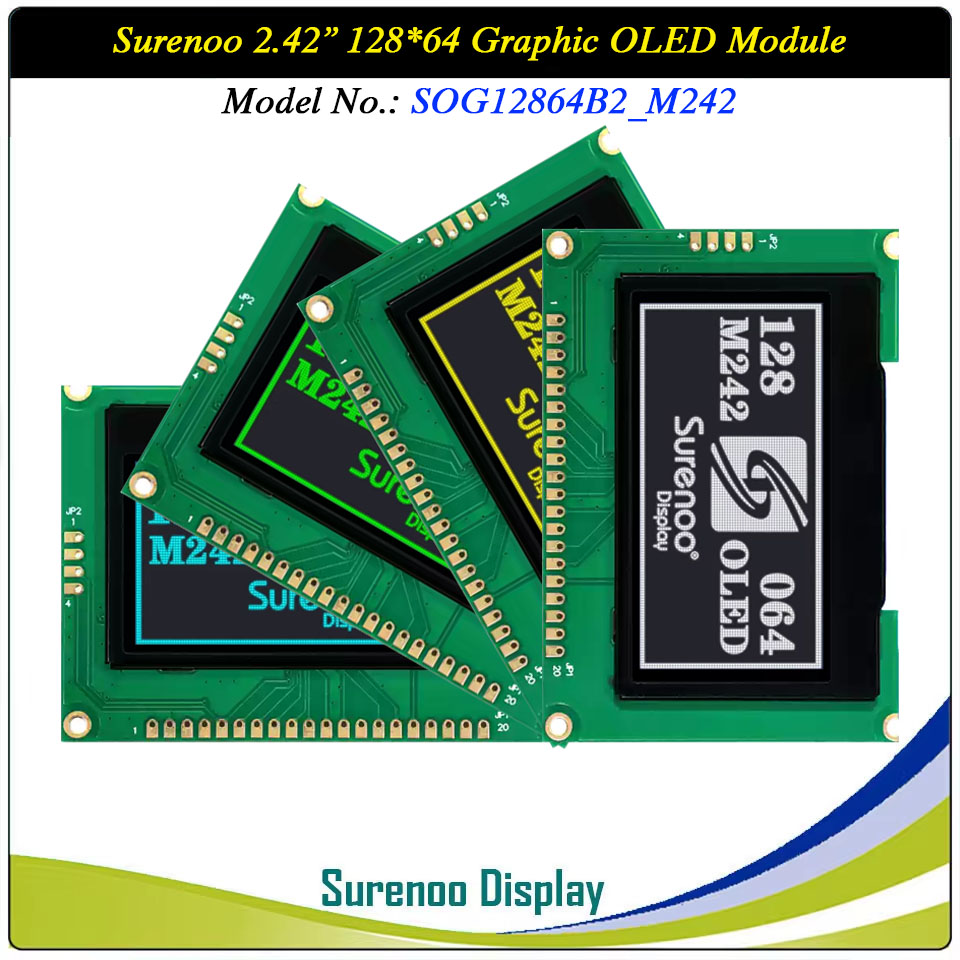
Surenoo Graphic OLED Module 75.00MMX52.70MM 2.42" 12864 128*64 128X64 Graphic LCD Module Display Screen Panel PM-OLED 6800/8080 8-Bit Parallel 4-Wire Serial SPI IIC I2C SSD1309 Controller SOG12864B2_M242
WISHLIST
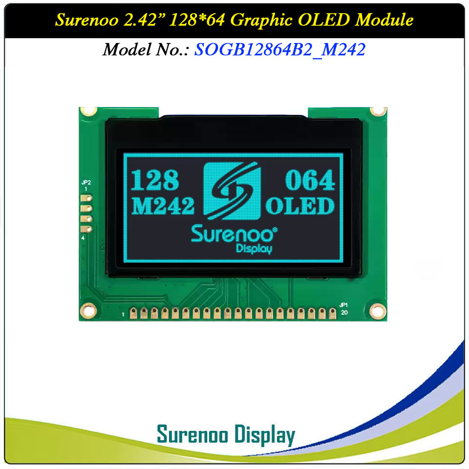
Display Size: 2.42"
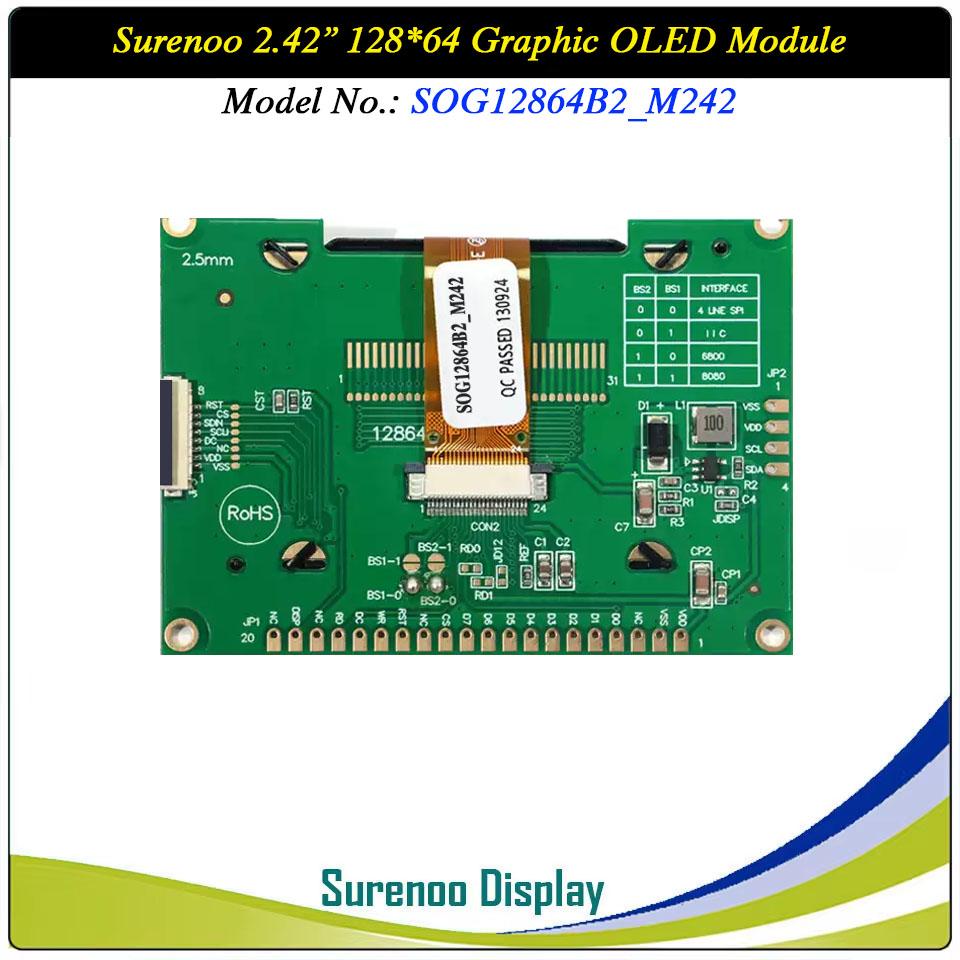
Model No.: SOG1286B2_M242
Display Format: 128*64 Dots
Outline: 75.00X52.70MM
Controller: SSD1309 or Equal
Model No.: SOG1286B2_M242
Display Format: 128*64 Dots
Outline: 75.00X52.70MM
Controller: SSD1309 or Equal
37 sold
Quantity
-
Detail
- Overview
- Specification
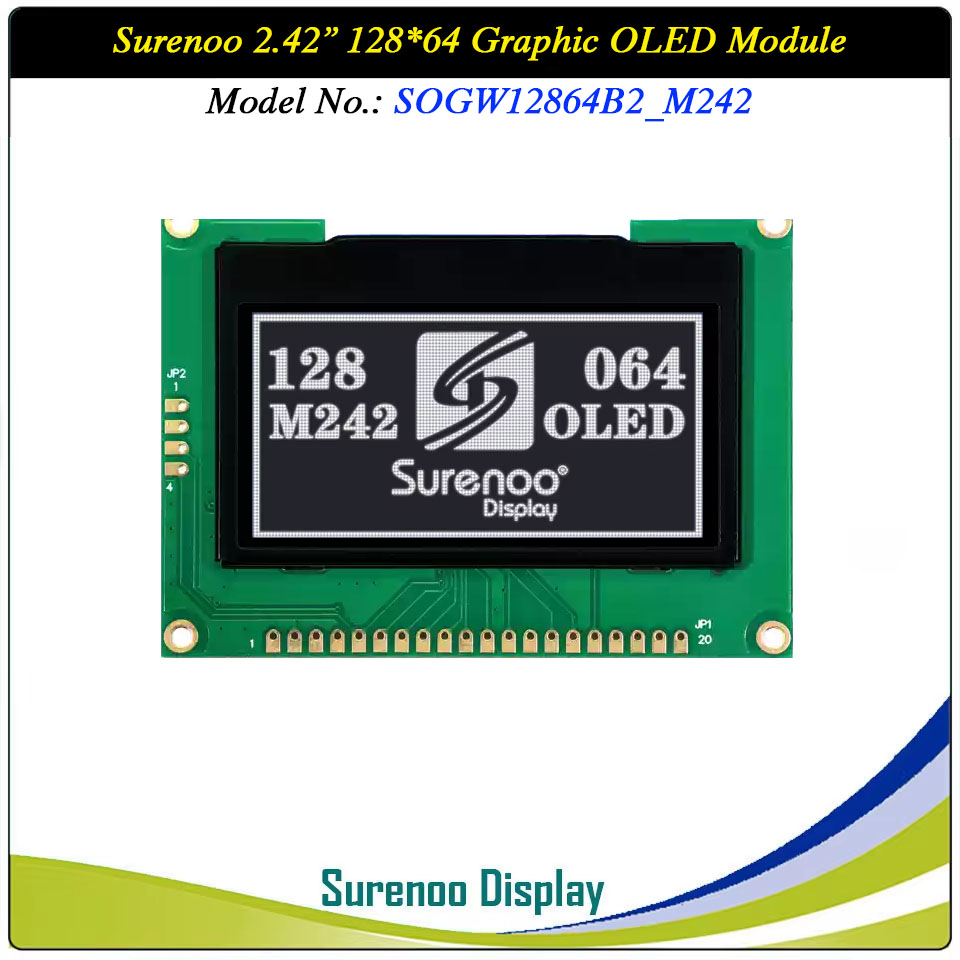
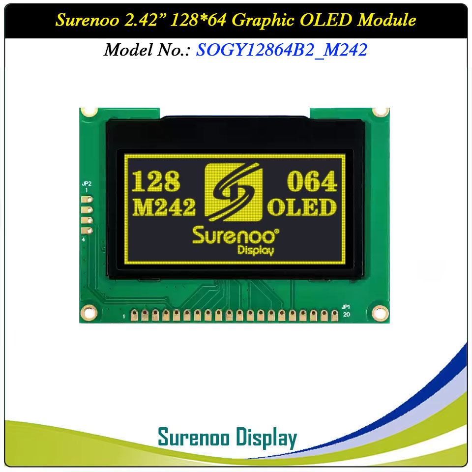
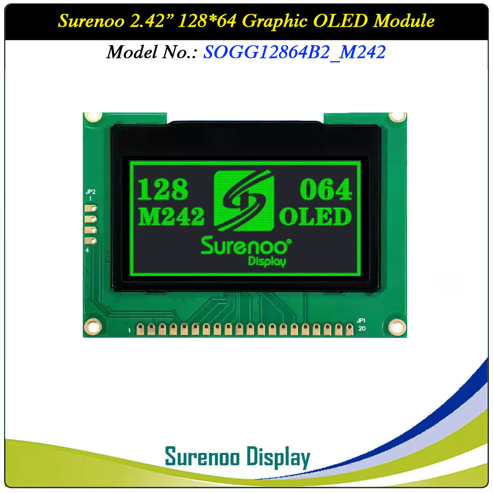
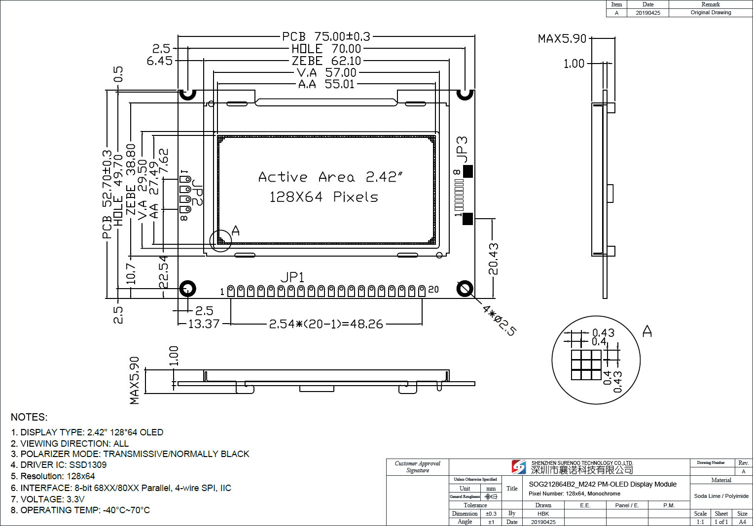
Gross Weight 0.040Kg Manufacturer Surenoo Display Type Graphic OLED Module Continuity Supply More than 10 years Part No. SOG12864B2_M242 Diagonal Size (Visual Area) 2.42" Display Format 128*64 Dots Interface 6800/8080 8-Bit Parallel, 4-Wire Serial SPI, IIC IC or Equivalent SSD1309 or Equal Voltage(Type) 3.3-5.0V Outline Dimension 75.00(W)x52.70(H)x5.90(T)mm Visual Area 57.01x29.49mm Active Area 55.01x27.49mm Dots Size 0.40x0.40mm Dots Pitch 0.43x0.43mm Display Type PM-OLED Panel Colors Code White(SOGW) / Yellow(SOGY) / Green(SOGG) / Blue(SOGB) IC Package COG Viewing Direction Full Viewing Angle Operating Temperature-40℃~70℃Storage Temperature-40℃~80℃- Outline Drawing (SOG12864B2_M242)
- Interface
Pin No. Symbol Description 1 VDD (3.3-5.0V) Power Supply for logic 2 GND (0V) Ground 0V 3 NC No Connection 4-11 D0-D7 Data Bus 12 /CS (L) This pin is the chip select input connecting to the MCU.The chip is enabled for MCU communication only when CS# is pulled LOW (active LOW).13 NC No Connection 14 /RES (H/L) This pin is reset signal input.When the pin is pulled LOW, initialization of the chip is executed. Keep this pin pull HIGH during normal operation.15 8080: WR (H/L) 6800: R/W (H/L) 8080: Active LOW Writed signal 6800: Read/Write: R/W=1: Read; R/W:=0: Write 16 D/C (H/L) This pin is Data/Command control pin connecting to the MCU. 17 8080: RD (H/L) 6800: E (H/L) 8080: Active LOW Read signal 6800: Operation enable signal. Falling edge triggered. 18 NC No Connection 19 DISP Display off when it's pulled low; Display on when it's pulled high. 20 NC No Connection
2. SOG12864B2_M242: JP2 <IIC (USE: R2 R5; NO USE: R3 R4; USE: R11~R20)>
Pin No. Symbol Description 1 GND (0V) Ground 0V 2 VDD (3.3-5.0V) Power Supply for logic 3 SCLK (H/L) Serial Clock signal 4 SDA (H/L) Serial Data input signal
3. SOG12864B2_M242: JP3 <4-Wire SPI: (USE: R3 R5; NO USE: R2 R4; USE: R11~R17)>Pin No. Symbol Description 1 GND (0V) Ground 0V 2 VDD (3.3-5.0V) Power Supply for logic 3 NC No Connection 4 D/C (H/L) This pin is Data/Command control pin connecting to the MCU 5 SCLK (H/L) Serial Clock signal 6 SDIN (H/L) Serial Data input signal 7 /CS (L) Chip Selection 8 /RST (H/L) Active LOW Reset signal -
Customer ReviewsNo comments