
Home
/
Surenoo HDMI Display
/
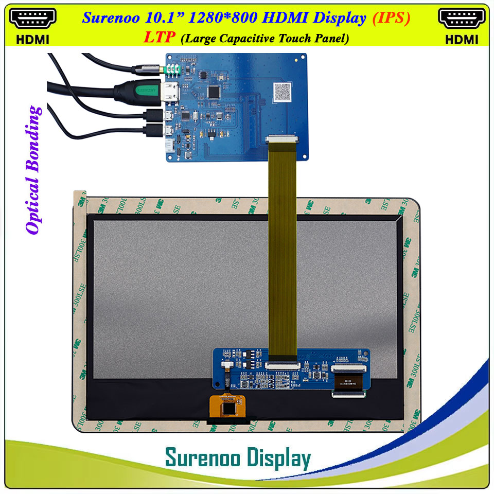
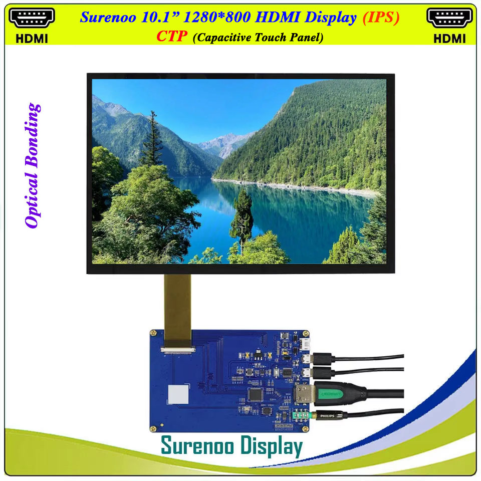
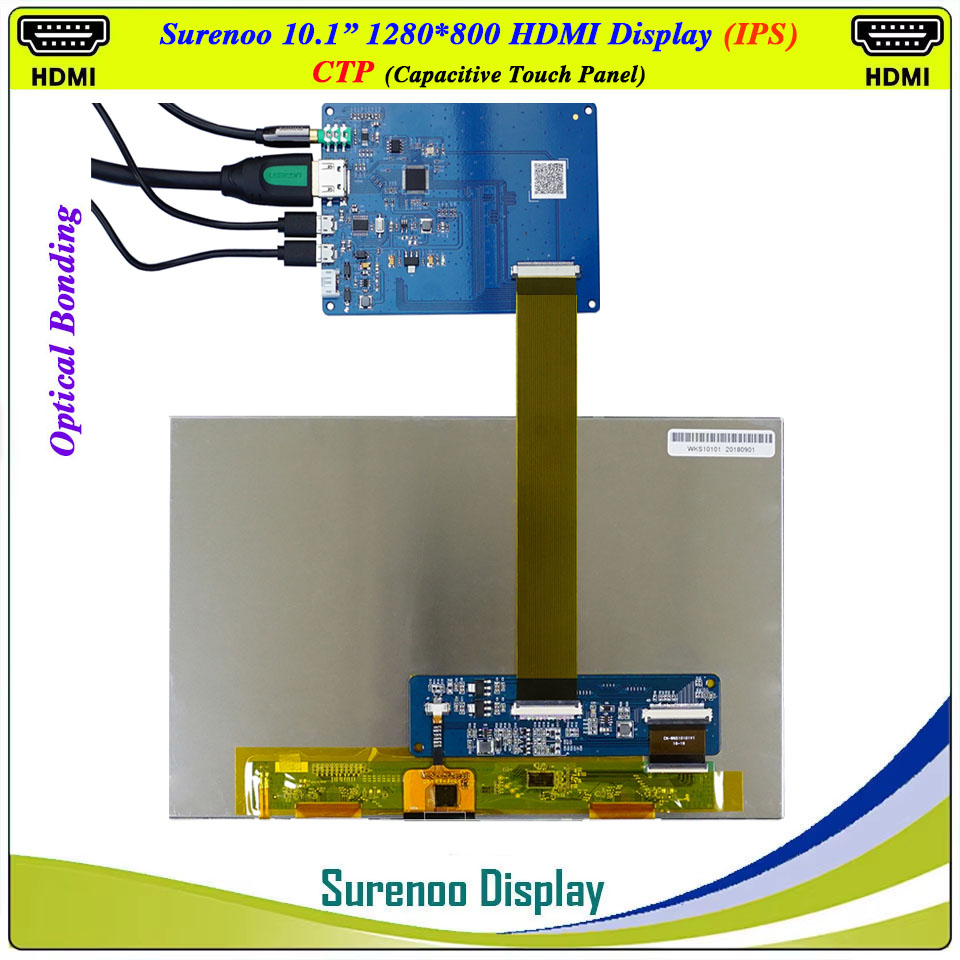
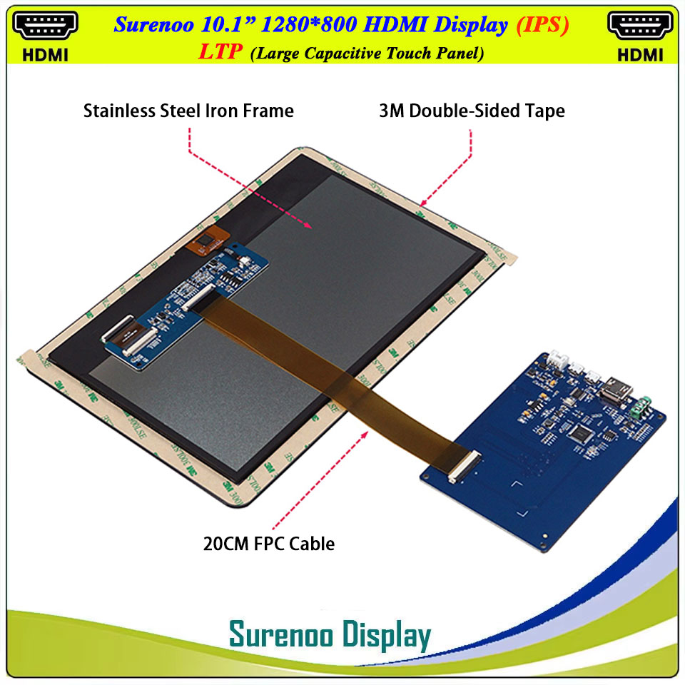
Surenoo HDMI Display 10.1" inch 1280*800 IPS LCD Display Module Screen Monitor with USB Optical Bonding Large Capacitive Touch Panel CTP LTP Support Audio Output and ATX 9-12V PWM Signal Brightness Adjustment for Windows Win10-11 RaspBerry Pi 4B/5
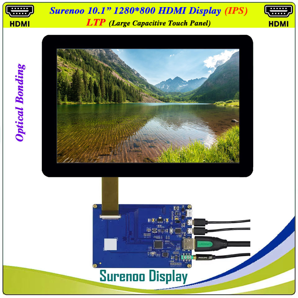
Surenoo HDMI Display 10.1" inch 1280*800 IPS LCD Display Module Screen Monitor with USB Optical Bonding Large Capacitive Touch Panel CTP LTP Support Audio Output and ATX 9-12V PWM Signal Brightness Adjustment for Windows Win10-11 RaspBerry Pi 4B/5
WISHLIST
Model No.: SHD101C-1280800
Model Size: 10.1 Inch
Resolution: 1280*800 IPS
Interface: HDMI
Touch Type: LTP/CTP
Model Size: 10.1 Inch
Resolution: 1280*800 IPS
Interface: HDMI
Touch Type: LTP/CTP
27 sold
Quantity
-
Detail
- Keywords
10.1" inch 1280*800 HDMI IPS LCD Monitors, Optical Bonding USB Capacitive Touch Panel, PWM Backlight Adjustment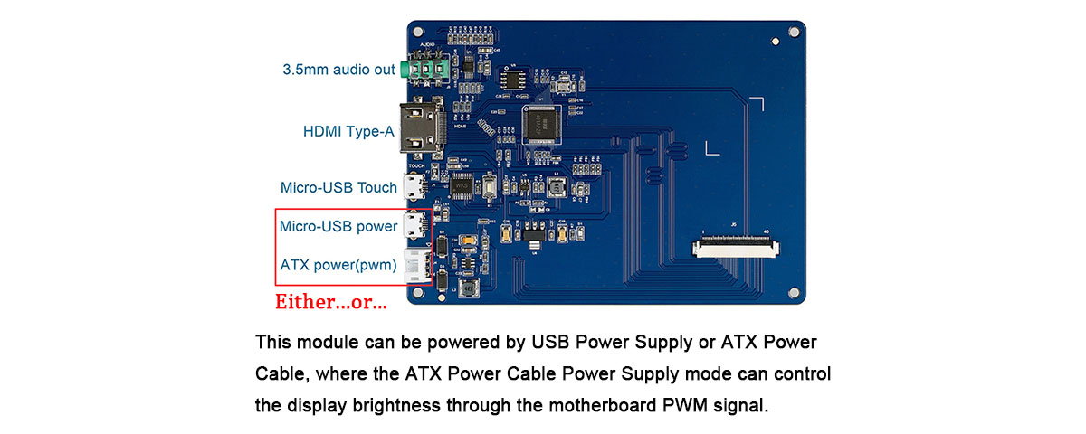
- Product Parameters
Item of General Information Contents Unit LCD Display Size (Diagonal) 10.1" Inch LCD Display Type TFT/TRANSMISSIVE - LCD Display Mode Normally Black - Recommended Viewing Direction IPS Full Angle O'Clock Model No. SHD101C-1280800-LTP - Resolutions 1280(RGB)*800 - Video Input Interface HDMI - Power Supply Double Micro USB 5.0V / ATX 9-12V - Touch Type USB 5-Points Large Capacitive Touch Panel (LTP) - Backlight Type White LED - Luminance(TYP) 300 CD/M2 LCM Module Size (W×H×T) CTP: 229.46×149.10 / LTP: 255.00×172.60 MM Active Area (W×H) 216.96×135.60 MM
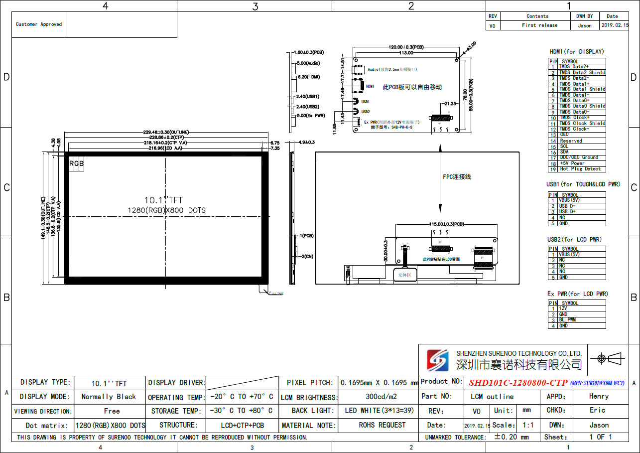
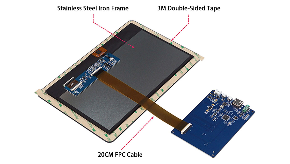
- External Dimensions
2. SHD101C-1280800-LTP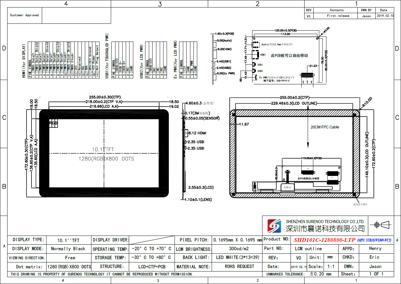
- Function & Interface
>> Pin Definition of HDMI Interface
PIN Symbol Function Description 1 TMDS Data2+ Positive side of channel 2 TMDS low-voltage signal differential input pair 2 TMDS Data2 Shield Ground 3 TMDS Data2- Negative side of channel 2 TMDS low-voltage signal differential input pair 4 TMDS Data1+ Positive side of channel 1 TMDS low-voltage signal differential input pair 5 TMDS Data1 Shield Ground 6 TMDS Data1- Negative side of channel 1 TMDS low-voltage signal differential input pair 7 TMDS Data0+ Positive side of channel 0 TMDS low-voltage signal differential input pair 8 TMDS Data0 Shield Ground 9 TMDS Data0- Negative side of channel 0 TMDS low-voltage signal differential input pair 10 TMDS Clock+ Positive side of reference clock. TMDS low-voltage signal differential input pair 11 TMDS Clock Shield Ground 12 TMDS Clock- Negative side of reference clock. TMDS low-voltage signal differential input pair 13 CEC No Connection 14 Reserved(N.C.) No Connection 15 SCL DDC SCL 16 SDA DDC SDA 17 DDC/CEC Ground Ground 18 +5V Power +5V Power 19 Hot Plug Detect Hot Plug Detect
>> Pin Definition of Micro USB PortTouch Function Power Fucntion PIN Symbol Function Description PIN Symbol Function Description 1 5.0V USB Power 1 5.0V USB Power 2 D+ USB Data+ 2 NC No Connection 3 D- USB Data- 3 NC No Connection 4 NC No Connection 4 NC No Connection 5 GND Power Ground 5 GND Power Ground
>> Pin Definition of ATX Pin HeaderPIN Symbol Function Description 1 9-12V External power input (9~12V) 2 GND Power Ground 3 PWM(EN) Backlight On/Off Control Input. A high input at EN turns on the converter, and a low input turns it off. When not used, connect EN to the input source for automatic startup. The EN pin cannot be left floating.
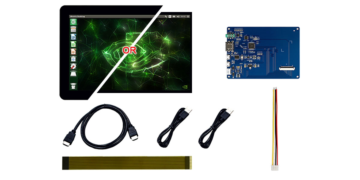
To use PWM dimming, apply a 200Hz to 1KHz square wave signal with amplitude greater than 1.5V to this pin.4 GND Power Ground - Packing List
-
Customer ReviewsNo comments