
Home
/
Surenoo MonoChrome Display
/
Surenoo Graphic OLED Module 3.83" 320132 320*132 320X132 Graphic LCD Module Display Screen Panel PM-OLED 4-Wire Serial SPI SSD1320 Controller SOG320132A_P383
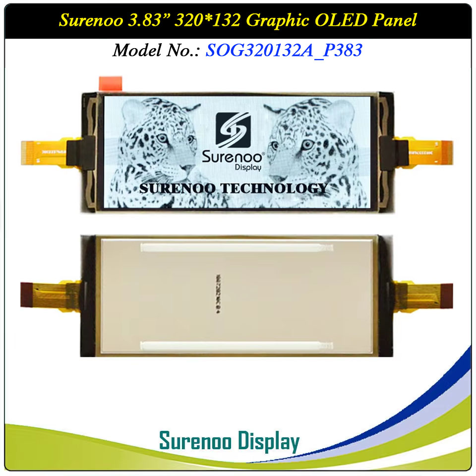
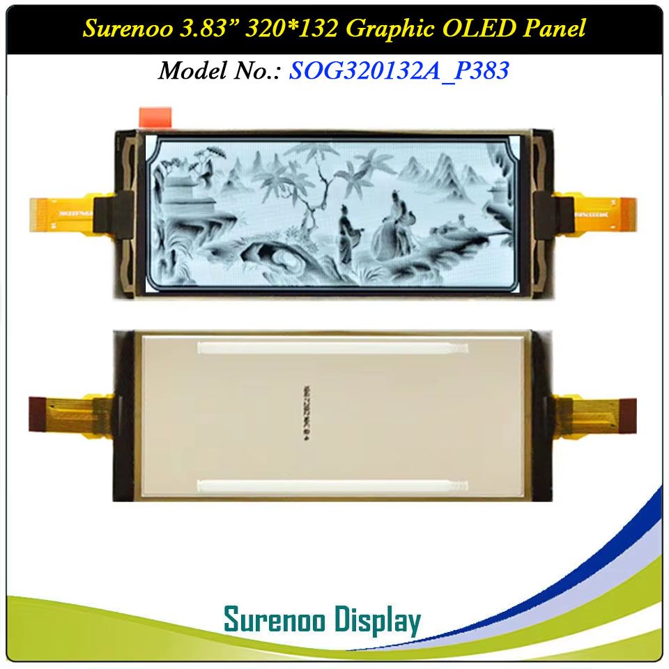
Surenoo Graphic OLED Module 3.83" 320132 320*132 320X132 Graphic LCD Module Display Screen Panel PM-OLED 4-Wire Serial SPI SSD1320 Controller SOG320132A_P383
WISHLIST
Display Size: 3.83"
Model No.: SOG320132A_P383
Display Format: 320*132 Dots
Outline: 105.52X41.67MM
Controller: SSD1320 X2 or Equal
Model No.: SOG320132A_P383
Display Format: 320*132 Dots
Outline: 105.52X41.67MM
Controller: SSD1320 X2 or Equal
11 sold
Quantity
-
Detail
- Overview
- Specification
Gross Weight 0.080Kg Manufacturer Surenoo Display Type Graphic OLED Panel Continuity Supply More than 10 years Part No. SOG320132A_P383 Diagonal Size (Visual Area) 3.83" Display Format 320*132 Dots Interface 4-Wire Serial SPI IC or Equivalent SSD1320 X2 or Equal Voltage(Type) 3.3V Outline Dimension 105.52(W)x41.67(H)x2.03(T)mm Visual Area 90.90x38.07mm Active Area 89.90x37.07mm Dots Size 0.281x0.281mm Dots Pitch 0.261x0.261mm Display Type PM-OLED Panel Colors Code White IC Package COG Viewing Direction Full Viewing Angle Operating Temperature-40℃~70℃Storage Temperature-40℃~80℃- Outline Drawing
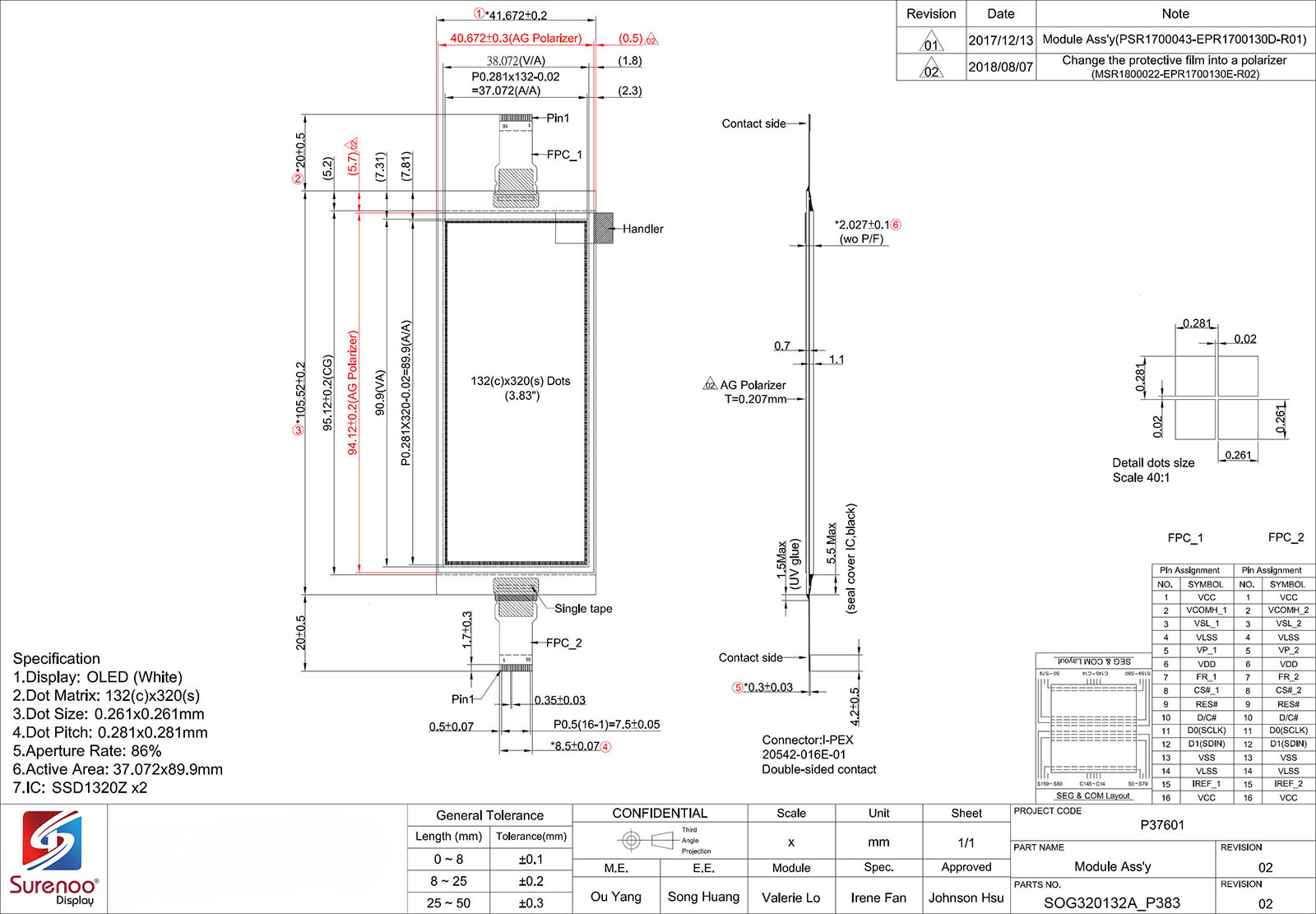
- Interface (FPC_1 & FPC_2)
Pin No. Symbol Description 1 VCC Power supply for panel driving voltage. 2 VCOMH_1 / VCOMH_2 COM signal deselected voltage level. 3 VSL_1 / VSL_2 This is segment voltage (output low level) reference pin. 4 VLSS Analog system ground pin. 5 VP_1 / VP_2 This pin is the segment pre-charge voltage reference pin. 6 VDD Power supply pin for core logic operation. 7 FR_1 / FR_2 This pin outputs RAM write synchronization signal. 8 CS#_1 / CS#_2 This pin is the chip select input connecting to the MCU. (active LOW) 9 RES# This pin is reset signal input. 10 D/C# This pin is Data/Command control pin connecting to the MCU. 11 D0(SCLK) The serial clock input: SCLK.12 D1(SDIN) The serial data input: SDIN.13 VSS Ground pin. 14 VLSS Analog system ground pin. 15 IREF_1 / IREF_2 This pin is the segment output current reference pin. 16 VCC Power supply for panel driving voltage. Please download the datasheet to get the detailed Pin description. -
Customer ReviewsNo comments