
Home
/
Surenoo Graphic OLED Display >> 128*64 Series
/
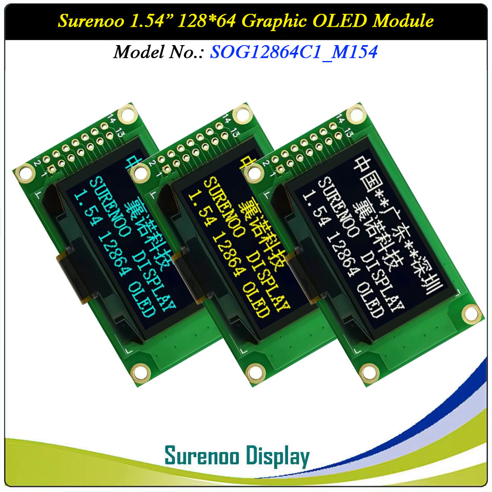
Surenoo Graphic OLED Module 1.54" 12864 128*64 128X64 Graphic LCD Module Display Screen Panel PM-OLED 6800/8080 8-Bit Parallel 4-Wire Serial SPI IIC I2C SSD1309 Controller SOG12864C1_M154
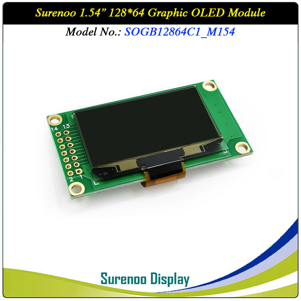
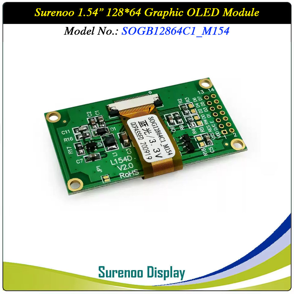
Surenoo Graphic OLED Module 1.54" 12864 128*64 128X64 Graphic LCD Module Display Screen Panel PM-OLED 6800/8080 8-Bit Parallel 4-Wire Serial SPI IIC I2C SSD1309 Controller SOG12864C1_M154
WISHLIST
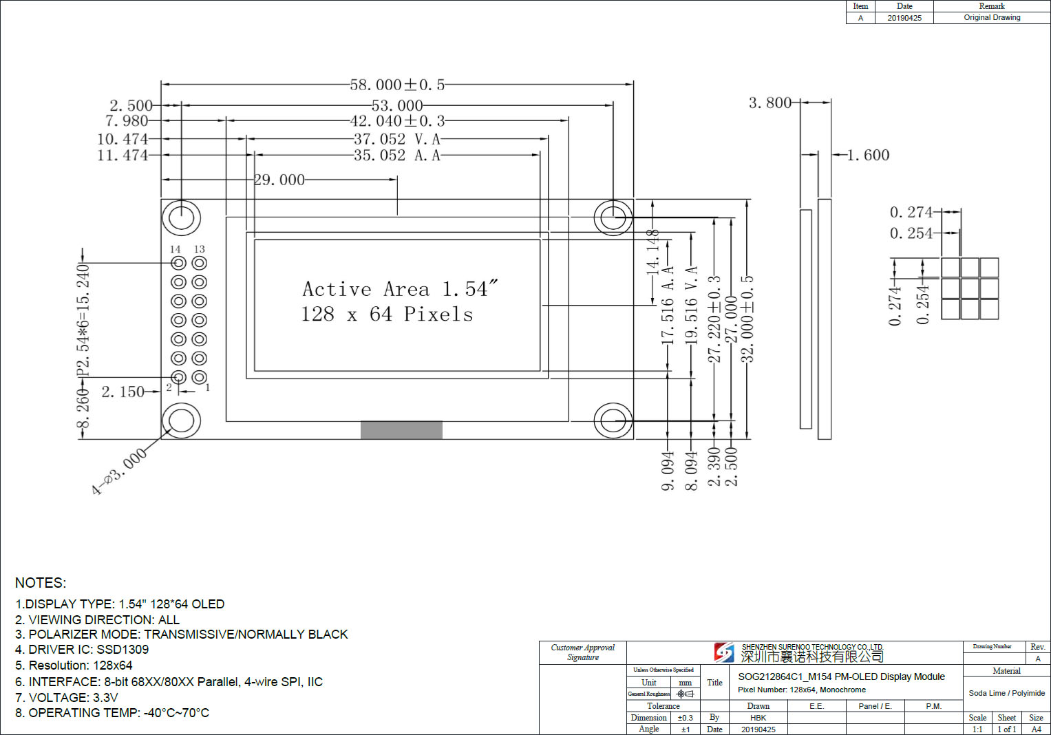
PCB Size is 58.00X32.00MM, the same as 0802 Standard Character LCD/OLED Module
Display Size: 1.54"
Model No.: SOG12864C1_M154
Display Format: 128*64 Dots
Outline: 58.00X32.00MM
Controller: SSD1309 or Equal
Model No.: SOG12864C1_M154
Display Format: 128*64 Dots
Outline: 58.00X32.00MM
Controller: SSD1309 or Equal
37 sold
Quantity
-
Detail
- Overview
- Specification
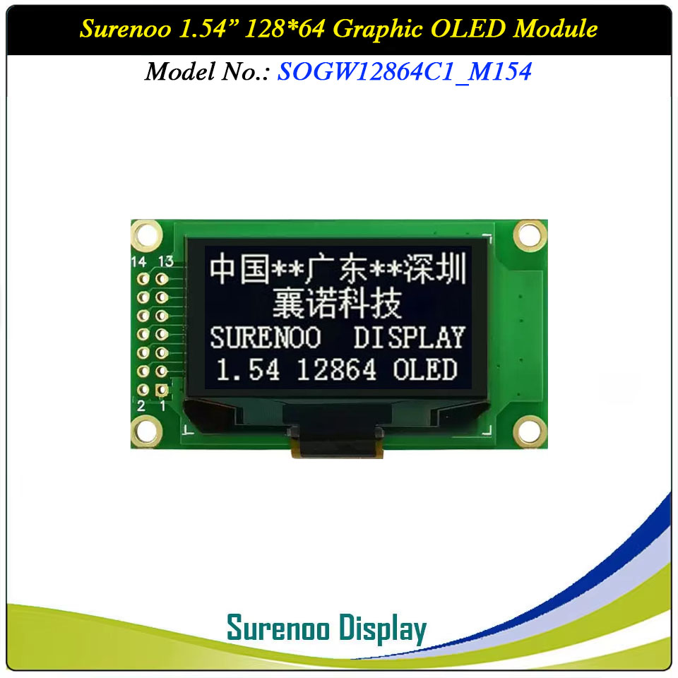
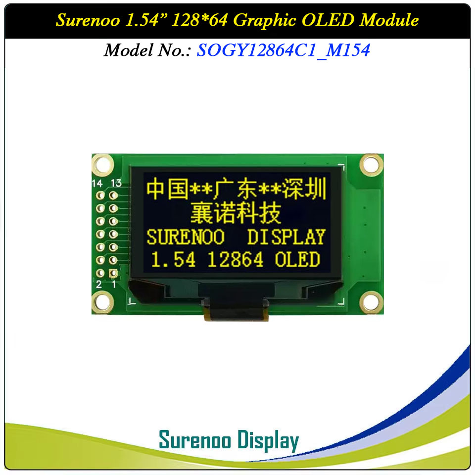
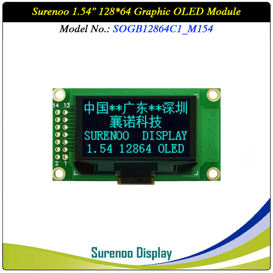
Gross Weight 0.040Kg Manufacturer Surenoo Display Type Graphic OLED Module Continuity Supply More than 10 years Part No. SOG12864C1_M154 Diagonal Size (Visual Area) 1.54" Display Format 128*64 Dots Interface 6800/8080 8-Bit Parallel, 4-Wire Serial SPI, IIC IC or Equivalent SSD1309 or Equal Voltage(Type) 3.3-5.0V Outline Dimension 58.00(W)x32.00(H)x3.80(T)mm Visual Area 37.052x19.516mm Active Area 37.052x17.516mm Dots Size 0.254x0.254mm Dots Pitch 0.274x0.274mm Display Type PM-OLED Panel Colors Code White(SOGW) / Yellow(SOGY) / Blue(SOGB) IC Package COG Viewing Direction Full Viewing Angle Operating Temperature-40℃~70℃Storage Temperature-40℃~80℃- Outline Drawing (SOG12864C1_M154)
- Interface
Pin No. Symbol Description 1 VSS (0V) Ground 0V 2 VDD (3.3-5.0V) Power Supply for logic 3 /RES (H/L) Active LOW Reset signal 4 D/C (H/L) H: Data L: Command 5 8080: WR (H/L) 6800: R/W (H/L) 8080: Active LOW Writed signal 6800: Read/Write: R/W=1: Read; R/W:=0: Write 6 8080: RD (H/L) 6800: E (H/L) 8080: Active LOW Read signal 6800: Operation enable signal. Falling edge triggered. 7-14 D0-D7 Data Bus
2. 4-Wire SPI: (USE: R3 R5; NO USE: R2 R4) / IIC (USE: R2 R5; NO USE: R3 R4)Pin No. Symbol Description 1 VSS (0V) Ground 0V 2 VDD (3.3-5.0V) Power Supply for logic 3 /RES (H/L) Active LOW Reset signal4 SPI: D/C (H/L) IIC: SA0 (H/L) SPI: H: Data L: Command IIC: Slave Address Selection signal 5-6 GND Ground 0V 7 SCLK(DB0) Serial Clock signal 8 SPI: SDIN(DB1) IIC: SDAIN(DB1) Serial Data Input signal IIC: Serial Data input signal (pins 11 and 12 can be tied together) 9 SPI: NC IIC: SDAOUT(DB1) No Connection IIC: Serial Data output signal (pin 12 can be no connect) 10-14 GND (D3-D7) Ground 0V -
Customer ReviewsNo comments