
Home
/
Surenoo Character OLED Display >> 1602 Characters
/
Surenoo COG OLED Module SOC1602F Outline=80.00X36.00MM 1602 16*02 16X2 Character LCD Module Display Screen Panel 6800/8080 8-Bit/4-Bit MPU Interface Serial 4-SPI I2C IIC SSD1311 Controller
Surenoo COG OLED Module SOC1602F Outline=80.00X36.00MM 1602 16*02 16X2 Character LCD Module Display Screen Panel 6800/8080 8-Bit/4-Bit MPU Interface Serial 4-SPI I2C IIC SSD1311 Controller
WISHLIST
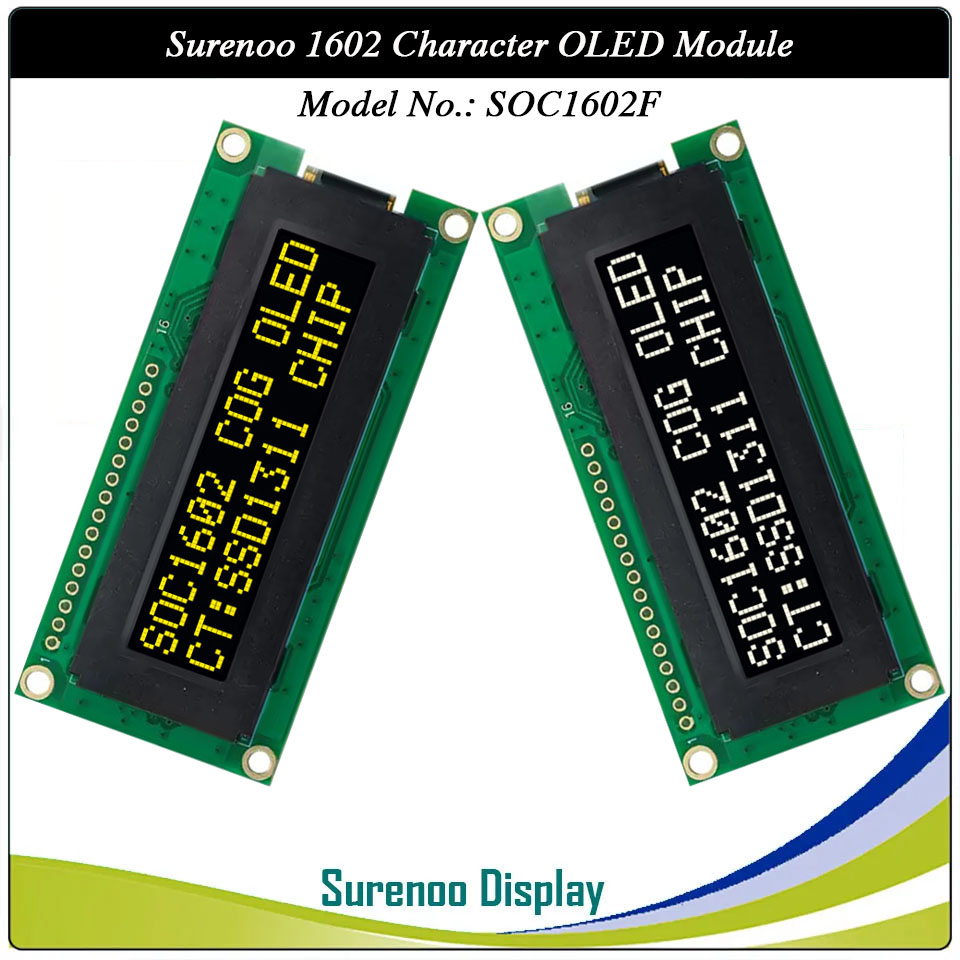
Model No.: SOC1602F OLED
Display Format: 16X02 Characters
Outline: 80.00X36.00MM
Controller: SSD1311 or Equal
Display Format: 16X02 Characters
Outline: 80.00X36.00MM
Controller: SSD1311 or Equal
18 sold
Quantity
-
Detail
- Overview
SSD1311 Buil-in character set supports English/Japanese, West European, Scandinavian European, and Cyrillic (Russian), see the KS0066 datasheet for the full character set.
It's easily controlled by MCU such as 8051, PIC, AVR, ARDUINO, ARM and Raspberry Pi. It can be used in any embedded systems, industrial device, security, medical and hand-held equipment.
- Specification
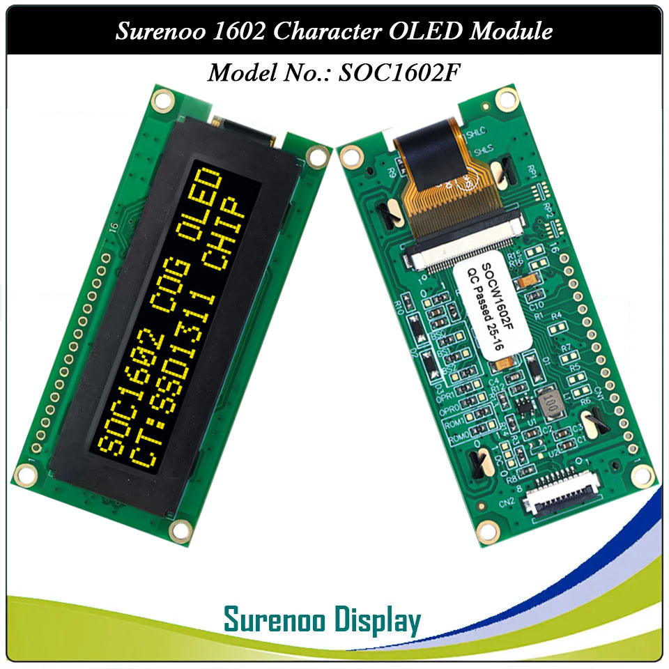
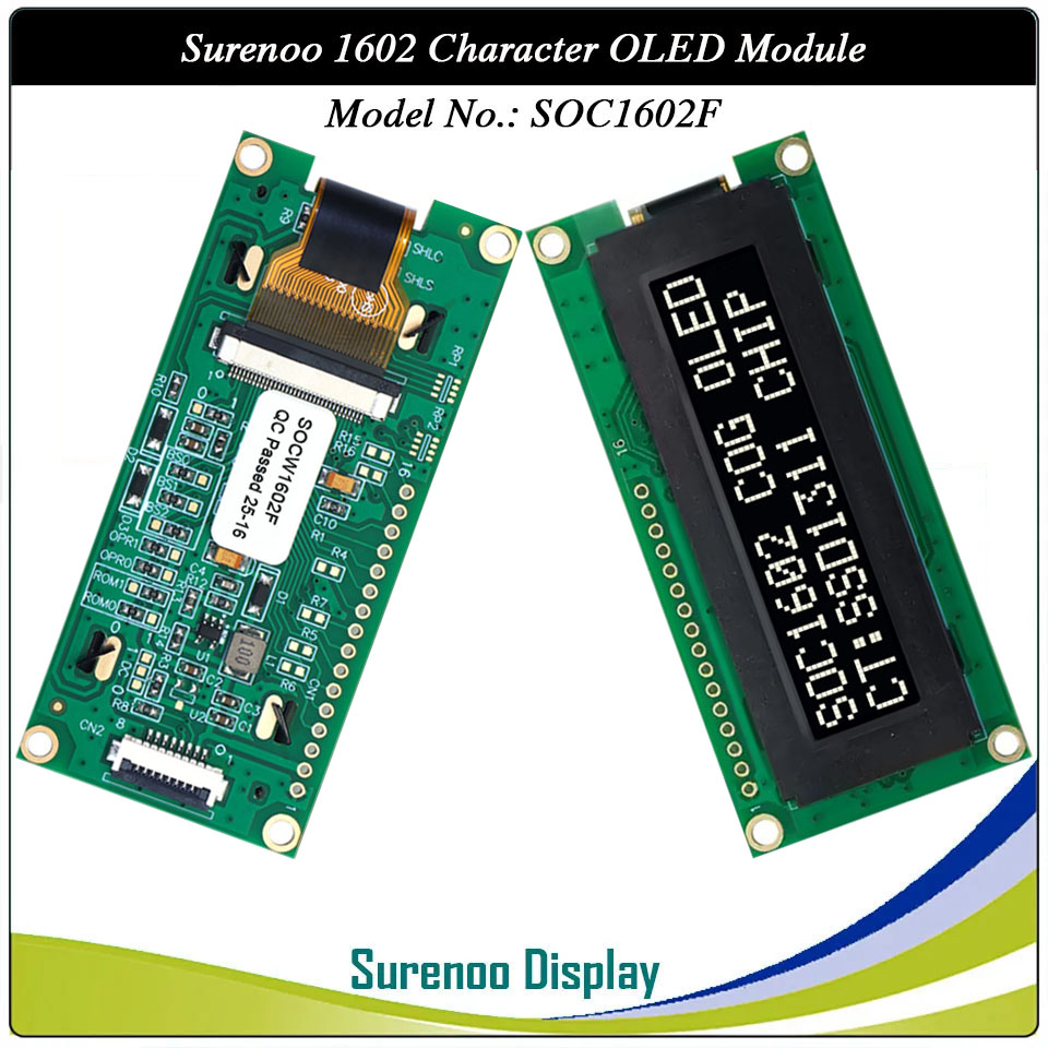
Gross Weight 0.032Kg Manufacturer Surenoo Display Type Character OLED Module Continuity Supply More than 10 years Part No. SOC1602F Display Format 16x2 Characters Interface 6800/8080 8-Bit/4-Bit MPU Interface, Serial 4-SPI, I2C IC or Equivalent SSD1311 or Equal Fonts English/Japanese, West European, Scandinavian European, and Cyrillic (Russian) Voltage(Type) 3.3-5.0V Connection 1*16P/2.54 Pin Header, 1*8P/1.0 FFC Connector Outline Dimension 80.00(W)x36.00(H)x9.30(T)mm Visual Area 58.00x13.30mm Active Area 56.22x11.52mm Display Type PM-OLED Panel Colors Code White(SOCW) / Yellow(SOCY) IC Package COG Viewing Direction Full Viewing Angle Operating Temperature-40℃~80℃Storage Temperature-40℃~85℃- Outline Drawing
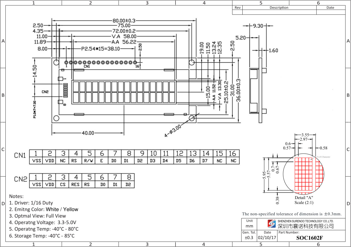
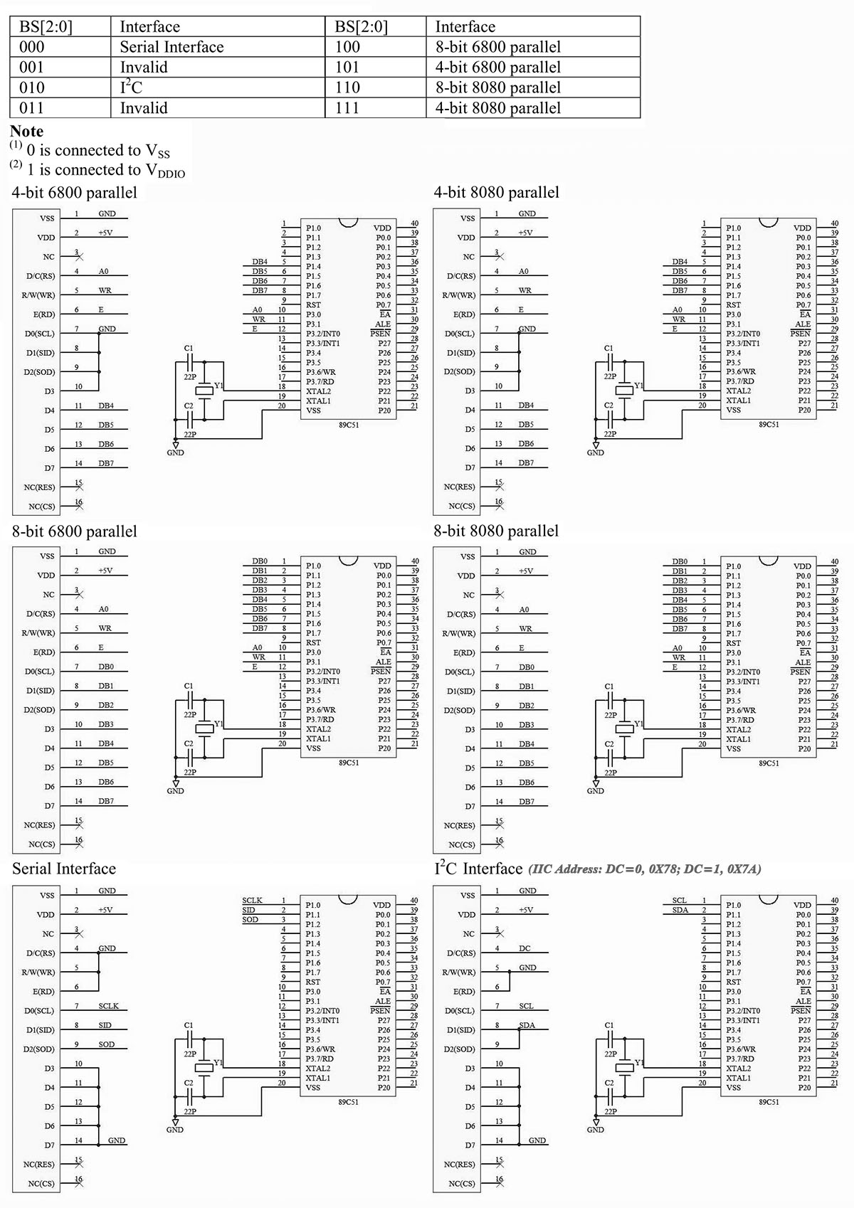
- Interface
Note:
1. R15=0Ω: CS,R16=0Ω: RES.
2. BS2=1, BS1=0, BS0=1: 4-6800 Mode;
3. BS2=1, BS1=1, BS0=1: 4-8080 Mode;
4. BS2=1, BS1=0, BS0=0: 8-6800 Mode;
5. BS2=1, BS1=1, BS0=0: 8-8080 Mode;
6. BS2=0, BS1=0, BS0=0: SPI Mode;
7. BS2=0, BS1=1, BS0=0: I2C Mode.Pin No. Symbol Level Description 1 GND 0V Ground 2 VDD 3.0-5.0V Power Supply for LCD 3 NC - No Connection 4 D/C(RS) I This pin is Data/Command control pin connecting to the MCU.
When the pin is pulled HIGH, the data at D[7:0] will be interpreted as data.
When the pin is pulled LOW, the data at D[7:0] will be transferred to a command register.
In I2C mode, this pin acts as SA0 for slave address selection.
When serial interface is selected, this pin must be connected to VSS.5 R/W(WR) I This pin is read / write control input pin connecting to the MCU interface.
When 6800 interface mode is selected, this pin will be used as Read/Write (R/W) selection input. Read mode will be carried out when this pin is pulled HIGH and write mode when LOW.
When 8080 interface mode is selected, this pin will be the Write (WR) input. Data write operation is initiated when this pin is pulled LOW and the chip is selected.
When serial or I2C interface is selected, this pin must be connected to VSS.6 E(RD) I This pin is MCU interface input.
When 6800 interface mode is selected, this pin will be used as the Enable (E) signal.
Read/write operation is initiated when this pin is pulled HIGH and the chip is selected.
When 8080 interface mode is selected, this pin receives the Read (RD) signal. Read operation is initiated when this pin is pulled LOW and the chip is selected.
When serial or I2C interface is selected, this pin must be connected to VSS.7-14 D0-D7 H/L These pins are bi-directional data bus connecting to the MCU data bus.
Unused pins are recommended to tie LOW.
When serial interface mode is selected, D0 will be the serial clock input: SCLK; D1 will be the serial data input: SID and D2 will be the serial data output: SOD.
When I2C mode is selected, D2, D1 should be tied together and serve as SDAout, SDAin in application and D0 is the serial clock inpu: SCL.15 NC(RES) - No connection (R15 NO) 16 NC(CS) - No connection (R16 NO) - Application Circuits
-
Customer ReviewsNo comments